GCSE Physics · Circuit practical
Series and Parallel Circuits Virtual Practical
Compare single, series and parallel arrangements using measured current and potential difference to test the rules for total resistance.
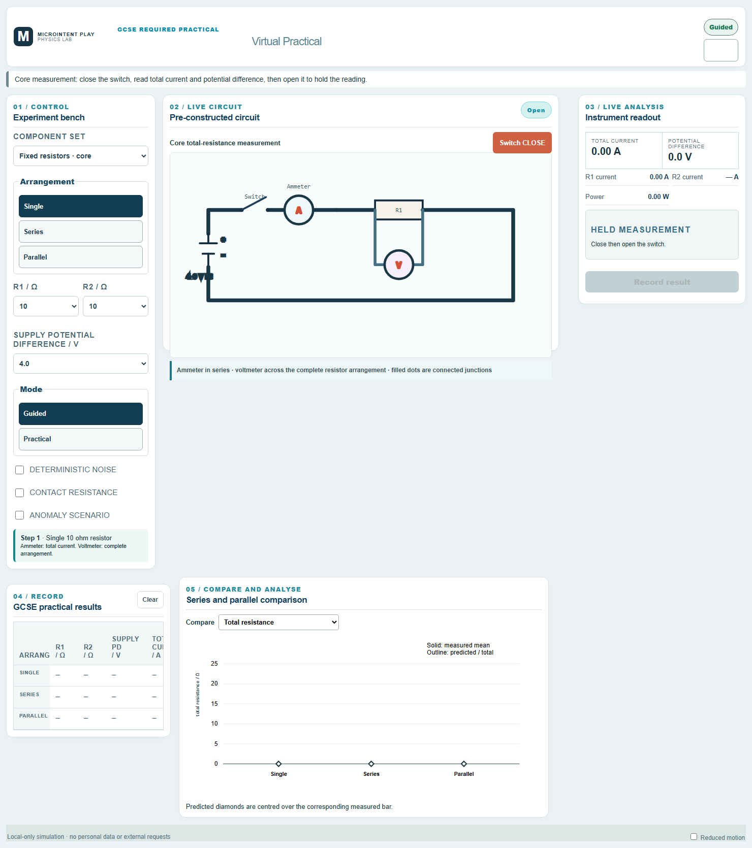
What you will investigate
This practical compares the behaviour of components in single, series and parallel arrangements. You measure total current and potential difference, then calculate total resistance.
The dashboard also predicts the total resistance from the component values, so measured and predicted results can be compared directly.
The fixed-resistor set is the core investigation. Filament lamps are available as an extension because their resistance changes as they heat.
Learning objectives
- Recognise series and parallel arrangements from a circuit diagram.
- Apply the current and potential-difference rules for each arrangement.
- Calculate total resistance from measured current and potential difference.
- Compare measured total resistance with the predicted value.
- Explain why parallel arrangements have a lower total resistance.
- Describe how filament lamps differ from fixed resistors.
Before you start
Apparatus
- Low-voltage DC power supply
- Switch, ammeter and voltmeter
- Fixed resistors of 5 Ω, 10 Ω and 15 Ω
- Connecting leads and crocodile clips
- Optional filament lamps for the extension
Safety
- Use a low-voltage supply and switch off between adjustments.
- Check meter ranges before closing the switch.
- Avoid short circuits and do not touch components that may be warm.
- Keep the working area clear of loose leads.
Method
Choose the arrangement
Select a single component, a series arrangement or a parallel arrangement. Identify the path of the current in each case.
Set the supply
Choose a supply potential difference and record it. Keep it constant when comparing arrangements.
Measure total current
Close the switch, read the ammeter in series with the arrangement, then open the switch.
Measure potential difference
Read the voltmeter connected across the complete arrangement. Record the value with the current.
Calculate total resistance
Use R = V / I for the complete arrangement. Record the measured total resistance.
Compare with prediction
Use the series and parallel rules to predict total resistance from the component values. Calculate the percentage difference.
Repeat and extend
Take repeats for each arrangement. Use the comparison chart to look for patterns, then test filament lamps if time allows.
The physics
In a series circuit, the current is the same at every point. The potential difference is shared between components in proportion to their resistance.
In a parallel circuit, the potential difference across each branch is the same. The total current is the sum of the branch currents.
The total resistance of a parallel arrangement is less than the resistance of the smallest branch because there are more paths for charge to flow.
A filament lamp is not ohmic: its resistance increases as the filament temperature rises. This makes its behaviour different from a fixed resistor.
R = V / ITotal resistance from the supply potential difference and total current.Rtotal = R1 + R2Series arrangement: total resistance is the sum of the component resistances.1 / Rtotal = 1 / R1 + 1 / R2Parallel arrangement: the reciprocal of total resistance is the sum of the reciprocals.P = V IElectrical power transferred by the circuit.Using the virtual practical
Guided mode
Guided mode walks through the measurement sequence and shows the expected current and potential difference for the selected arrangement.
Practical mode
Practical mode lets you read the meters and record results independently, with optional noise, contact resistance and anomaly scenarios.
What the dashboard records
- Component set, arrangement and resistor values
- Supply potential difference and meter readings
- Measured and predicted total resistance
- Percentage difference and repeats
- Comparison chart for resistance, current and potential difference
Results and analysis
Relationship
Series arrangements have a larger total resistance than the individual components; parallel arrangements have a smaller total resistance than the smallest branch.
Graph
Use the comparison chart to compare measured and predicted total resistance across single, series and parallel arrangements.
Conclusion
State whether the measured results support the series and parallel rules, and explain any differences in terms of meter resolution, contact resistance or component behaviour.
Common misconceptions
- Current is used up as it flows around a series circuit.
- The current is the same at every point in a series circuit. Energy is transferred, but charge is not used up.
- Adding a resistor in parallel increases total resistance.
- Adding a parallel path decreases total resistance because the total current increases for the same potential difference.
- The potential difference is the same across every component in a series circuit.
- In series, the potential difference is shared. In parallel, it is the same across each branch.
- Filament lamps obey Ohm's law.
- A filament lamp is non-ohmic because its resistance changes with temperature.
Teacher notes
The fixed-resistor set provides a clean comparison between measured and predicted values. Filament lamps are included as an extension to discuss non-ohmic behaviour.
Read the full teacher notes for Series and Parallel Circuits
Interactive dashboard
Run the practical
Guided mode walks through the measurement sequence and shows the expected current and potential difference for the selected arrangement.
- Runs locally in the browser
- Keyboard, mouse and touch support
- Reduced-motion preference respected
- No account or personal data required