GCSE Physics · Required practical
Current–Potential Difference Characteristics
Measure current at a range of signed potential differences for a resistor, filament lamp and diode, then compare their characteristics.
What you will investigate
This practical investigates how the current through a component changes as the potential difference across it changes. You build a characteristic graph for each component.
A fixed resistor gives a straight line through the origin. A filament lamp curves because its resistance changes with temperature. A diode conducts in one direction only.
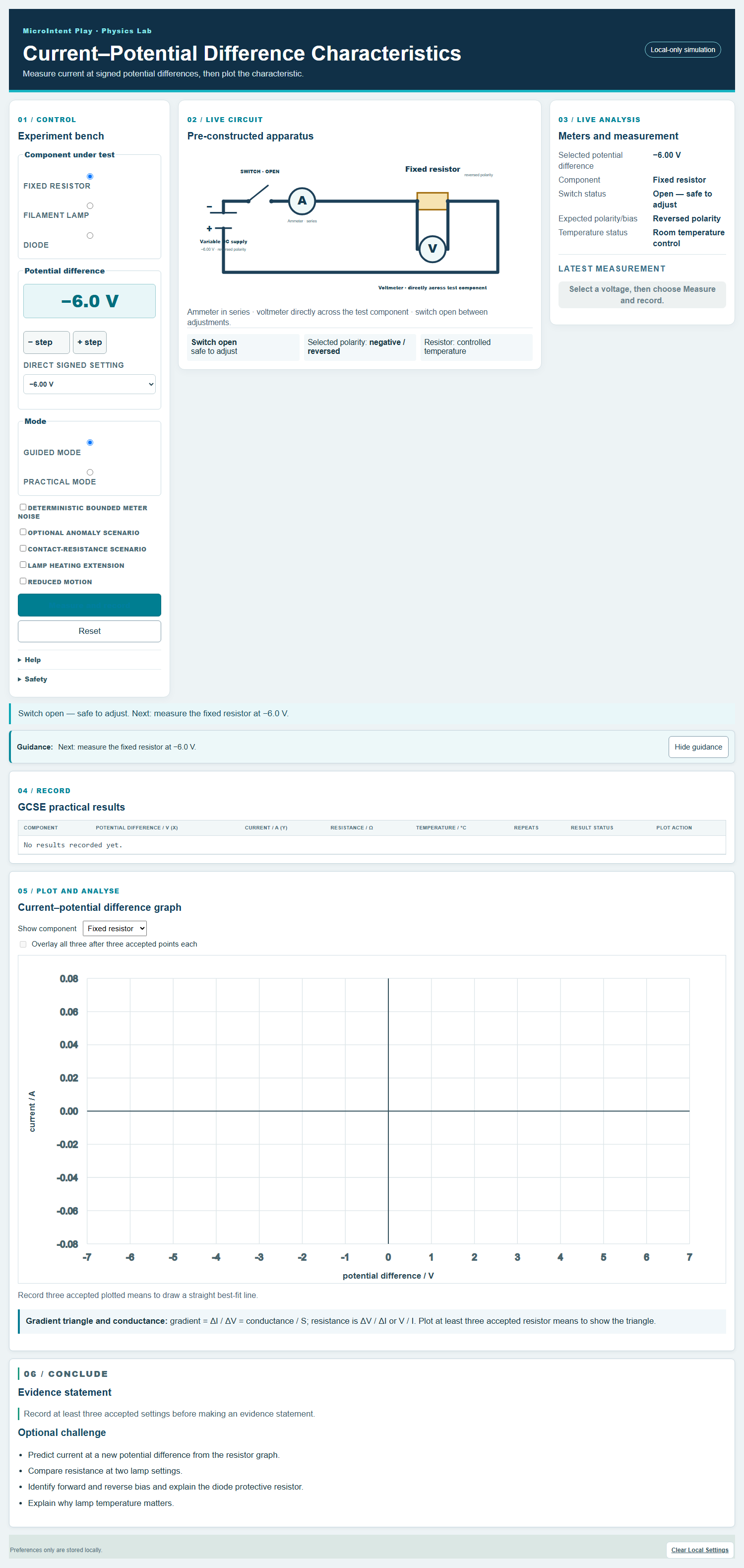
The circuit is pre-constructed so that the focus stays on measurement, signed values and interpretation of the graph.
Learning objectives
- Measure current at a range of positive and negative potential differences.
- Record signed values and plot a current–potential difference graph.
- Describe the characteristic of a fixed resistor, filament lamp and diode.
- Calculate resistance at a selected operating point.
- Explain the effect of temperature on a filament lamp.
- Explain forward and reverse bias for a diode.
Before you start
Apparatus
- Variable low-voltage DC supply
- Switch, ammeter and voltmeter
- Fixed resistor, filament lamp and diode
- Protective resistor for the diode
- Connecting leads and crocodile clips
Safety
- Use a low-voltage supply and switch off between adjustments.
- The filament lamp can become hot; allow it to cool before handling.
- Always use a protective resistor with the diode.
- Check meter ranges and avoid reverse connection damage.
Method
Choose the component
Select the fixed resistor, filament lamp or diode. Check that the circuit is connected correctly for that component.
Set a potential difference
Adjust the supply to the first value. The switch should be open while you change the setting.
Measure and record
Close the switch, read the ammeter and voltmeter, then open the switch. Record both signed values.
Repeat across the range
Take readings at regular intervals, including negative values where appropriate. Allow the lamp to cool between readings.
Take repeats
Repeat key readings and calculate a mean where the values are consistent. Exclude readings that are clearly anomalous.
Plot the characteristic
Plot current on the y-axis against potential difference on the x-axis. Join the points with a smooth curve or a line of best fit.
Compare the components
Describe the shape for each component and explain what it shows about resistance and conduction.
The physics
A fixed resistor at constant temperature has a straight-line characteristic through the origin. Its resistance is constant, so it is an ohmic conductor.
A filament lamp has a curved characteristic because the filament temperature rises with current. Its resistance increases as it gets hotter.
A diode conducts only when it is forward biased above a threshold potential difference. In reverse bias, the current is very small.
Resistance at a point is V / I, not the gradient. The gradient of an I–V graph is conductance, the reciprocal of resistance.
V = I RAt a selected point on the characteristic, resistance is V / I.R = V / IResistance at an operating point; it is not the gradient of an I–V graph.P = V IPower transferred at a selected operating point.gradient = ΔI / ΔVThe gradient of an I–V graph is conductance, not resistance.Using the virtual practical
Guided mode
Guided mode calculates the expected current for the selected component and potential difference, helping learners check their readings and the sign convention.
Practical mode
Practical mode asks learners to read the meters and record signed values independently, with optional noise, anomaly and heating scenarios.
What the dashboard records
- Component under test and selected potential difference
- Signed ammeter and voltmeter readings
- Resistance at the operating point
- Repeats, anomalies and plotted means
- Current–potential difference graph for each component
Results and analysis
Relationship
The shape of the characteristic identifies the component: a straight line for an ohmic resistor, a curve for a filament lamp, and one-directional conduction for a diode.
Graph
Plot current on the y-axis and potential difference on the x-axis. Use the same scale for each component if you want to compare them directly.
Conclusion
Describe each characteristic, calculate resistance at a chosen point, and explain the physical reason for any curvature or one-directional behaviour.
Common misconceptions
- All components obey Ohm's law.
- Only ohmic conductors at constant temperature have a constant resistance. Filament lamps and diodes do not.
- The resistance of a filament lamp is constant.
- The filament temperature changes with current, so the resistance changes too.
- A diode conducts equally well in both directions.
- A diode conducts in forward bias above a threshold and allows very little current in reverse bias.
- The gradient of an I–V graph is the resistance.
- The gradient is conductance. Resistance at a point is V / I.
Teacher notes
The diode always includes a protective resistor in the model. The lamp heating extension makes the temperature dependence explicit rather than hidden.
Read the full teacher notes for Current–Potential Difference
Interactive dashboard
Run the practical
Guided mode calculates the expected current for the selected component and potential difference, helping learners check their readings and the sign convention.
- Runs locally in the browser
- Keyboard, mouse and touch support
- Reduced-motion preference respected
- No account or personal data required