GCSE Physics · Required practical
Resistance of a Wire Virtual Practical
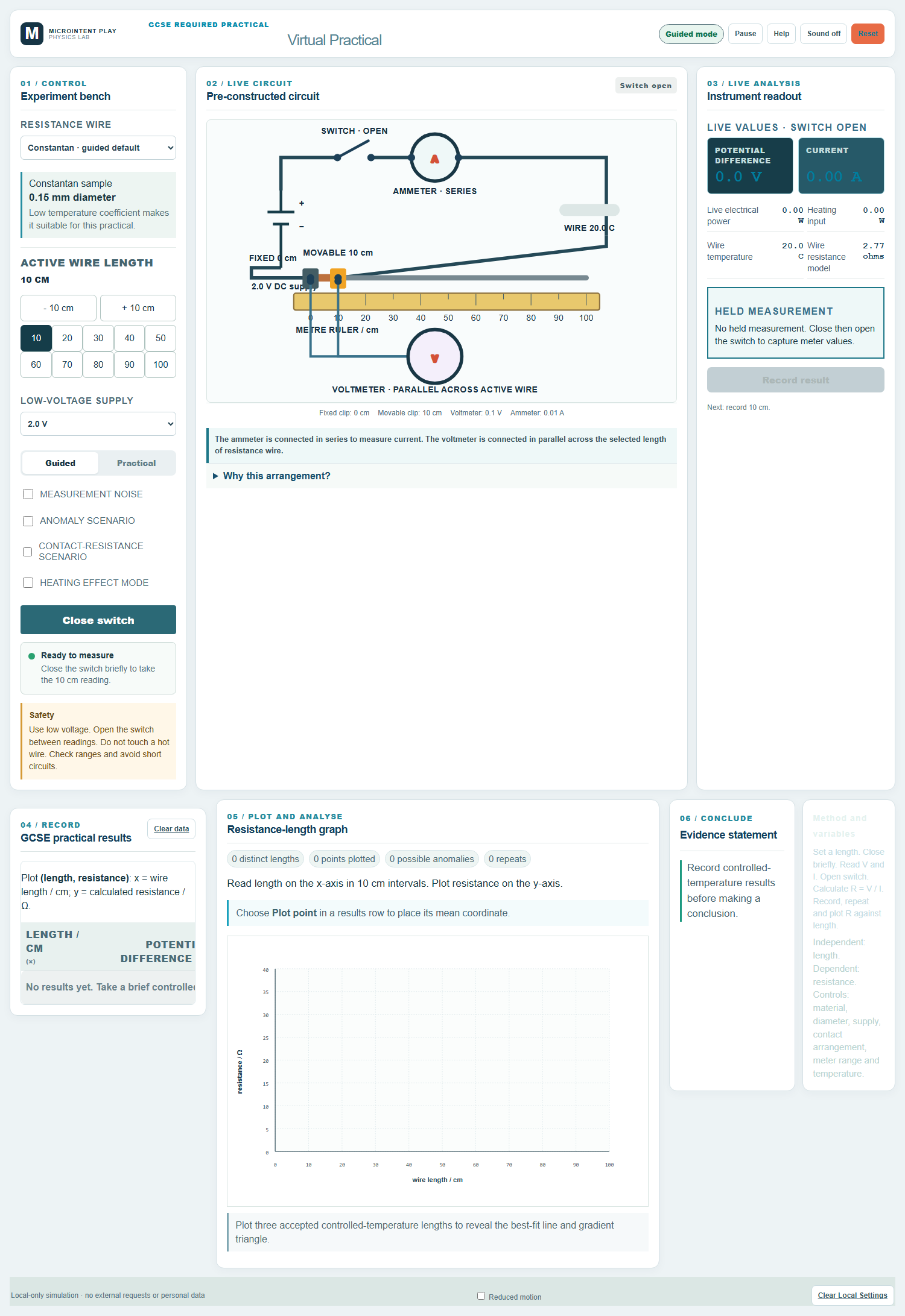
Change the length of a wire in a pre-built circuit, read the ammeter and voltmeter, and use R = V / I to investigate resistance.
What you will investigate
This practical investigates how the resistance of a wire depends on its length. The circuit is already connected so that the lesson can focus on measurement, calculation and analysis.
The independent variable is the length of the wire between the crocodile clips. The dependent variable is the resistance calculated from the voltmeter and ammeter readings.
The material, diameter, supply setting and temperature are controlled. The ammeter is in series and the voltmeter is in parallel across the selected length of wire.
Learning objectives
- Interpret a circuit with an ammeter in series and a voltmeter in parallel.
- Calculate resistance using R = V / I.
- Control the variables that affect resistance.
- Plot resistance against length and describe the relationship.
- Use the gradient to discuss resistivity and wire geometry.
- Recognise the effects of heating and contact resistance.
Before you start
Apparatus
- Mounted constantan or nichrome wire with a metre rule
- Low-voltage DC power supply
- Switch, ammeter and voltmeter
- Crocodile clips and connecting leads
- Optional thermometer or temperature guidance
Safety
- Use a low-voltage supply and switch off between adjustments.
- Close the switch only long enough to take a reading.
- The wire may become warm; do not touch it until it has cooled.
- Check meter ranges and avoid short circuits.
Method
Select the wire
Choose the wire sample and confirm its material and diameter. These must stay constant for a fair test of length.
Set the length
Place the crocodile clips at the first measured length on the metre rule. Record the length in centimetres.
Close the switch briefly
Close the switch, read the ammeter and voltmeter, then open the switch. Keeping the current brief limits heating.
Calculate resistance
Use R = V / I with the meter readings. Record the resistance and the length that produced it.
Repeat and change length
Take a repeat reading, then increase the length in equal steps. Allow the wire to cool if it has warmed.
Plot resistance against length
Plot resistance on the y-axis and length on the x-axis. Draw a best-fit line and calculate its gradient.
Evaluate the evidence
Check whether the line passes through the origin. A non-zero intercept may indicate contact resistance or a systematic error.
The physics
For a wire of constant material and cross-sectional area, resistance is directly proportional to length. Doubling the length doubles the resistance.
The gradient of a resistance–length graph is ρ / A. It is not the resistance itself.
Heating increases resistance for most metals, so readings taken at high current can drift. Brief readings and cooling time protect the evidence.
Contact resistance at the crocodile clips can produce a small non-zero intercept. This is a useful discussion point rather than a failure of the practical.
V = I RPotential difference, current and resistance in a circuit.R = V / ICalculate resistance from the voltmeter and ammeter readings.R = ρ L / AResistance depends on resistivity, length and cross-sectional area.A = π r²Cross-sectional area of a wire with radius r.Using the virtual practical
Guided mode
Guided mode calculates resistance from the selected length and displays the expected meter readings. It is useful for checking the relationship before independent measurement.
Practical mode
Practical mode asks you to read the meters and record the values yourself. It keeps the measurement and decision-making steps visible.
What the dashboard records
- Wire material, diameter and selected length
- Ammeter and voltmeter readings
- Calculated resistance and repeats
- Excluded or too-warm readings
- Resistance–length graph and gradient
Results and analysis
Relationship
Resistance should increase in proportion to length when material, diameter and temperature are controlled.
Graph
Plot resistance on the y-axis and length on the x-axis. The gradient has units of ohms per unit length and can be converted to ohms per metre.
Conclusion
Describe the relationship, quote the gradient with units, and evaluate whether the intercept and scatter are consistent with the measurement method.
Common misconceptions
- The voltmeter should be connected in series.
- The voltmeter is connected in parallel across the component; the ammeter is in series with it.
- Resistance depends on the current flowing through the wire.
- For an ohmic conductor at constant temperature, resistance is a property of the wire. Current and potential difference change together.
- The gradient of a resistance–length graph is the resistance.
- The gradient is resistance per unit length, related to resistivity and area. Resistance is the y-value at a given length.
- A longer wire has less resistance.
- For the same material and diameter, a longer wire has more resistance because charge carriers travel through more material.
Teacher notes
The circuit is deliberately pre-constructed so that the virtual practical focuses on measurement, control variables and analysis rather than drag-and-drop wiring.
Interactive dashboard
Run the practical
Guided mode calculates resistance from the selected length and displays the expected meter readings. It is useful for checking the relationship before independent measurement.
- Runs locally in the browser
- Keyboard, mouse and touch support
- Reduced-motion preference respected
- No account or personal data required